 Using simulation to determine the right valve gate sequence.
Article From: MoldMaking Technology, Tim Lankisch , Director of Engineering from CAE Services
In a previous article (MMT, January 2013) we talked about using flow simulation to help determine the best gate locations and how to size them properly. We said that one of the driving factors in determining gate locations was the aesthetics of the part. Undesirable effects such as knit lines and the visibility of the gate vestiges could significantly limit gate placement and ultimately control the processibility of the mold.
Sometimes, those processing limitations can include pressure and/or clamp force limitations. Indeed, there seems to be a growing trend of trying to process molds in smaller and smaller machines. Along with that trend (maybe coincidentally?) there has been a proliferation of the use of sequential valve-gating (a.k.a. SVG) in hot manifolds.
Moldmakers have recognized its benefits in helping them design more robust molds. Molders have recognized the freedom and control that SVG has afforded them to improve the filling patterns and overall processibility of their molds. However, along with that freedom and control come some challenges. The use of flow simulation (done properly) can help to overcome those challenges by providing the following three benefits:
- Helps moldmakers determine the number and location of hot drops
- Determining the best timing sequence for opening and shutting valve pins
- Reduced pressure and/or clamp force requirements
Determining Number and Location of Hot Drops
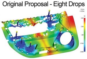
Suppose you are involved in a project like the one shown below (see Figure 1). You have been given the task of determining how to gate this mold. Not an easy task, for sure. If we asked 10 different mold designers about how to gate it, we’d probably get 10 different answers.
Now let’s add to the challenge and say that you must use direct gates, and you can’t have any knit lines in the map pocket area. How will you tackle that one? Experience can only get you so far, and relying on mental moldflow can end up costing your company a lot of money and time in rework, so it is important to get help from simulation—especially in cases like this that have less margin for error.
As analysts, we either start with a generic estimate of how many hot drops would be required to fill the mold or the number of drops is dictated to us. Often times, these initial scenarios are dictated by the project budget and the analyst has to work with what they are given. In our example, we were given an 8-drop scenario without sequencing, which caused a prominent knit line in the map pocket. In the other cases, the initial number of drops is usually dictated by the maximum flow distance that is recommended for a given material.
Once all the initial ideas have been laid out, it’s time to do some preliminary simulations and see which of the ideas looks the most promising. In order to judge which scenario is best, the following questions should all be answered “Yes”:
- Is there adequate spacing between the drops for tool construction?
- Can the mold be filled with reasonable pressure?
- Can the part be packed adequately within the machine’s clamp force limit?
- Have major knit lines been eliminated or moved into acceptable locations?
- Is the manifold turnover ratio less than 1?
- Is the warpage acceptable?
- Are the shear rates in the gates acceptable, especially in the first gate that fires?
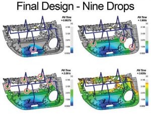
If the answer is “No” to any of those questions, it may require adjusting the locations of the drops slightly or it may require adding more drops. Every project is different. Sometimes the trade-offs for keeping the number of drops unchanged are insignificant enough to be ignored. After many iterations of changing the design and answering those questions, we determined that nine drops were necessary for our example, using the valve-gate sequence shown.
Determining the Best Timing Sequence for Opening and Shutting Valve Pins
There are three basic patterns for sequencing valve gates: center-out, cascaded and multi-cavity.
In the center-out scenario, filling usually starts from a single nozzle/gate near the center of the part and proceeds outward toward the next tier of drops, which is usually two, but could be more drops located approximately equidistant from the first drop. The advantage of this scenario is that it requires the least filling time, and usually the least pressure and clamp force. Center-out sequencing is also very good for eliminating knit lines near the center of the part, which is often the most visible area.
For cascaded sequencing, filling starts at one end of the part from a single nozzle and proceeds across the part with successive drops firing one by one. This method requires more filling time and usually requires more pressure and clamp force, but in many cases it can result in less warpage, especially with glass fiber-filled materials. Having those glass fibers aligned in one direction can improve the material’s shrinkage uniformity as well as its strength in one direction.
For multi-cavity molds, sequencing can be used to properly fill and pack several cavities that have very different overall size and/or wall stock. For example, one can begin filling a larger cavity while a smaller cavity is shut off. Once the larger cavity is nearly filled—or even during packing—the other cavity can be turned on to fill and pack out in-sync with the first cavity.
The importance of simulation cannot be stressed enough for this type of situation, especially when more than two cavities are involved. Using simulation allows us to determine if it’s even possible, and then helps determine the appropriate timing for opening/shutting valve pins for proper filling and packing.
For any of these three scenarios, hot drops may feed into cold runners and edge gates, sub gates or cashew gates. In these cases, valve gate timing is critical for avoiding backflow into the cold gate and runner. The simulation analyst is able to tell exactly when the valve gate should open to allow the flow from a cold runner/gate to join the advancing melt front with minimal backflow. In fact, it is possible to trigger a valve gate to open when the flow front reaches a pre-defined location on the part. Simulation can also trigger valve gate opening by time, pressure or ram position on the molding machine.
The benefits of using a timing sequence are not limited to the filling stage; they can be applied to the packing stage too. There are many cases where a manifold and timing sequence design creates a beautiful filling pattern, only to lead to overpacking in one particular cavity or area of a part. Strategically shutting off selected nozzles during the packing stage can help avoid this problem, which makes packing more uniform and can help reduce the overall clamp force requirement.
Reduced Pressure and Clamp Force Requirements
So, exactly how does valve gate sequencing reduce pressures to fill a mold? I like to think of it as a relay race. In the Olympics, for example, there are four equal legs of a relay race, each of which is covered by a different runner. In the 4 x 100, each runner runs 100 meters, and each leg requires roughly equal effort from each runner. Now, imagine if there was only one runner to cover the entire 400 meters. It would require significantly more effort from that one runner.
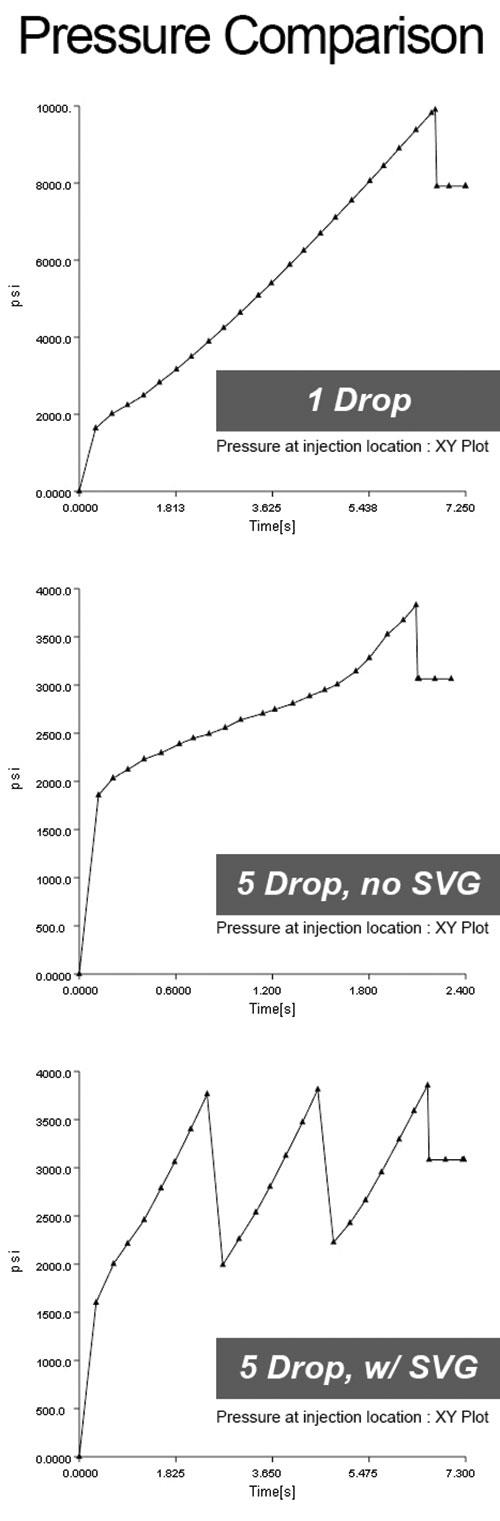
The same goes for valve-gate sequencing. Each successive valve gate that opens picks up where the previous gate left off and reduces the required injection pressure. In Figure 2 we see graphically how this works out. In simulation, we can use this graph to help balance out the pressure peaks and reduce the overall filling pressure requirement, thus equalizing the effort required of each nozzle.
The benefits of reduced clamp force usually come when comparing the single gate scenario to the multiple gate scenario. In both cases you avoid knit lines, but the single drop scenario requires significantly more clamp force. It also results in non-uniform packing, whereby the center of the part is severely overpacked while the end-of-fill areas are underpacked. This shrinkage variation leads to warpage in the part. When we compare two multiple drop scenarios (SVG vs. no SVG) with the same number of drops in the same locations, the clamp force results are fairly similar and the packing is relatively uniform, but the SVG version has no knit lines.
Summary
As you can see, being a control freak in the injection molding world isn’t such a bad thing when it comes to designing your molds. Control of the filling pattern is just one of the many benefits of using valve-gate sequencing in an injection mold. The extra expense of these manifolds can be quickly justified in many ways when you realize how much more freedom and control it can afford you. Those additional costs can be minimized when you leverage the use of flow simulation along with it to place the nozzles and gates correctly and to determine the right timing sequence. But, as always, make sure that the simulation is being done by qualified engineers that have extensive background with valve-gate sequencing.